
Application Notes-307
Power Factor Correction (PFC) Testing
1. Reason:
Recently, due to the popularity of electronic and computer
product, as well as the increase awareness of environmental protection
issue, therefore it has been listed as a
improvement item.
Normally power source (exclude battery)
for electronic and computer product comes through from public utility power
system. Its power source's circuitry structure is using diode rectifier,
filter then pass through current transformation circuitry, as shown in
figure 1, even though this method will make the voltage waveform becomes
positive waveform rectifying diode and filtering capacitor, the rectifying
diode short at the instant where the AC voltage is higher than the voltage
on the filtering capacitor, causing intermittent current flow which result
in an impulse waveform effect, this is the reason why harmonic current and
power factor are below (usually 0.6- 0.7).
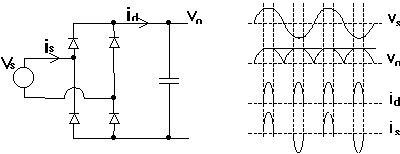
Figure 1.
Above result and ideal non-harmonic current
(power factor of 1.0) has an apparent difference, it cause the efficiency of
power consumption to be lower. For example in table 1, usual power supply
has a power factor of 0.65 when obtaining power from public utility power
system with 1440 VA capacity, it can load up to maximum power of 702W.
However, for the power supply with PFC function, it can reach up to power
factor of 0.99 with load up to maximum power of 1015W. European CE mark has
already require product with power consumption more than 300W (will be
reduce in the future) to meet their harmonic current limit requirement, that
means the power factor has to increase (about > 0.95) in order to meet CE
requirement before a product can be market to Europe. Right now, countries
other than one in
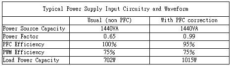
Table 1
Table 1 compare between power supply using traditional rectifier circuitry and PFC correction circuitry. In a traditional 15A - 120V public power circuit, UL require that under 15A circuit breaker capacity, its continues rms current value must be lower than 12A, so to meet UL safety requirement. That means there is only 1440VA usable capacity, but consider typical energy transformation efficiency and poor power factor, there is only 702W of power can be given to load, (1440*0.75*0.65=702W). However, for the power supply with PFC front-end circuitry, it can improve to 1015W of power transferable to load.
From these we can see that improving equipment power factor can improve power consumption and reduce harmonic interference, in addition this will reduce the urgency for building new power plant. Under the increase importance of environmental protection trend, PFC does seem meaningful.
2. Application:
Traditional electrical product like motor with inductance, its power factor increase depends on connecting parallel capacitor to shows resistance on the load, it also increase performance. However nowadays, electronic and computer product belongs to rectifying type load, its current waveform does not like inductive type load remains like sine wave, it has a impulse waveform, therefore it cannot just rely on parallel capacitor to improve the power factor.
Actually, to increase power factor for
rectifying type loading electronic and computer product, there are passive
and active type power factor correction.
Passive type use inductor (figure 2), capacitor (figure 3) circuitry to
reduce harmonic current, because power source frequency is 50Hz or 60Hz low
frequency, it needs large inductor and capacitor, also the power factor
improvement is not as good, limited improvement result, that is why it is
rarely use.
Figure 2 input terminal inductance working frequency is power source frequency (50/60 Hz), due to the fact that inductor can soften the current sudden change, therefore the input current waveform will be smoother. Figure 3 is using partly smoothen circuitry structure, to improve power factor. Its theory is extend the period where the voltage of the power source is higher than output voltage range, according to diode turn on condition, input current waveform will become smoother.
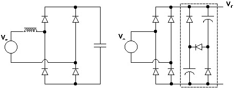
Figure 2: Passive type filtering inductor power factor correction circuit
Figure 3: adding partly smoothen capacitor's
power factor correction circuit
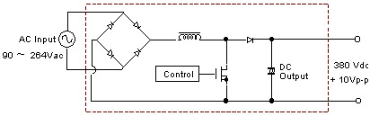
Active type power factor correction using active component (control circuit
and power sine conductor ON/OFF switch) as shown in figure 4.
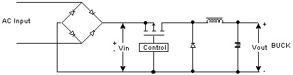
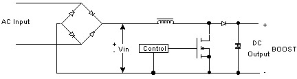
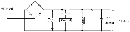
Its fundamental working theory is to adjust input current waveform to looks like input voltage waveform, this can reach the point where power factor of 1 goal. Right now there are several chip manufacturer offer PFC control IC, just need to add few parts like power Mosfet, inductor and few other little component to make a active power factor regulator, such as figure 4 (b) BOOST structure power factor correction as voltage step up type, that is input voltage range can be 90Vdc to 264V without additional switch for choosing the voltage range. To have a universal voltage model, this power factor regulator is a very important additional value, and this power factor regulator output of 380Vdc has a 10Vp-p and 50/60Hz harmonic & high frequency noise.
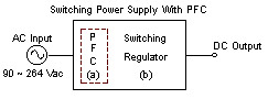
Power supply with PFC included as shown in Figure 5 and Figure 6.
PFC Circuit
Figure 6 PFC Circuit
3. Testing Technique:
3.1 When examine power supply with PFC included (Figure 5), need to do a few test on the input and output.
These include input line regulation of PFC: When input voltage change, the rate of change to input power factor.
Output load regulation of PFC: When load current change, the rate of change to input power factor.
Combine regulation of PFC: When input voltage and output load change at the same time, the rate of change to input power factor.
3.2 Above input voltage change can use auto-transformer or AC power source to change input voltage to simulate possible actual change, for example 90~115~132 or 180~230~264 or 90~115~264 or 90~230~264 different voltage combination.
3.3
Input power measurement require accurate power meter, such as
Prodigit's 4010/4011 accurate power meter, this
meter need to have consistent accuracy within 90V~264V voltage range in
order to have a trustful result under different input current.
3.4 On output load, one can use DC electronic load to simulate different load conditions.
3.5 Above is using adjustable power source for testing, to examine PFC function. That is indirect examine method, because when load change, it is going through Figure 5(b) switching regulator, if the switching regulator experience any abnormal conditions, this will affect the examine result on Figure 5(a) PFC Block. This testing method is more suitable in testing the final product in production line.
3.6 Therefore we are going to introduce another testing method. Take out the PFC section as shown in figure 6 and do the test individually on it. Now we use 500v high voltage electronic load to simulate Figure 5(b) switching regulator and DC output current, so we can more accurately examine the power factor regulator with input voltage, output load and combination input power factor correction rate. Now we only need use a high voltage electronic load (like Prodigit model 3253, 3254, 3255, 3500 product), then we can examine the function of the power factor regulator and do test directly. This testing method is suitable for R&D to verify on PFC function and testing, it is also suitable for production to test on PFC section.
4. Testing Technique:
Prodigit Electronic always devoted to developing of power electric testing equipment, we have the best and complete solution in all necessary equipment for PFC testing: Accurate digital power meter and high voltage 500V electronic load.
Accurate digital power meter model 4010/4011 simultaneously digitally sampling the voltage and current waveform, according to RMS, watt and PF theory, using microprocessor to compute 0.1% accuracy's RMS voltage, current watt and <0.002 accuracy's power factor, it is highly accurate and consistent under the widest voltage and current range, this is the most accurate and reasonable price's power meter in the market.
High voltage 500V electronic load model 3253, 3254, 3255 is Prodigit specially design 500V electronic load for PFC output testing, 3253 is design for 300W or below, 3254 is specially design for 1200W or below, and 3255 is for up to 1800W testing load.
Above high voltage electronic load has constant current and constant resistant mode, has voltage, current, power and VA meter, allow you easily read PFC's output voltage, current, power, and then compare with the input measure by the digitizing power meter, this way the PFC efficiency can be calculate, also there is model 3500 for 5KW or below testing.
Above PFC testing equipment are used by
several power supply manufacturer with good result, please contact company
sales if you have any need of these equipment.