
Application Notes-402
4010/4011 Digitize Meter Improvements description
1. Voltage measuring part:
This portion is from original single input circuit (figure1) change into differential input circuit (figure2).
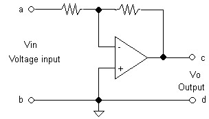
Figure 1: single input circuit block diagram
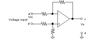
Figure 2: differential input circuit block diagram
1.1. Advantage for the change:
1.1.1. It can be more accurately when measuring voltage across load: After changing the single input circuit into differential input voltage measuring circuit, we can measure the voltage on the load without voltage drop across the cable which decreases the accuracy. It becomes apparent especially when there are large load current or long cable connection. The difference is describe in figure 3, original single input circuit can only measure the voltage across the 4010/4011 rear panel's load input connector (voltage V1 or terminal a-b in figure 3), if measuring load has large current or long cable connection, its voltage drop across the cable can not be compensate, which will cause inaccuracy. As for differential circuit, it can solve this problem, together with suitable cable connection, it can measure load side's input circuit (Load voltage V2 or Load terminal a'-b' in Figure 3), therefore above large current or long cable connection error can be eliminated
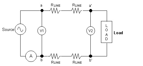
Figure 3 differential input can eliminate test circuit's voltage drop in cable
1.1.2. Easier Calibration:
During calibration 4010/4011 power meter, it needs voltage and current input in order to calibrate correctly, also because 4010/4011 use real time A/D voltage and current waveform sampling technique, (similar to digital oscilloscope CH 1, CH 2, sampling simultaneously), therefore voltage and current need to be in same phase in order to meet the normal test connection and loading condition. (Actually meter calibrator is used to simulate actual condition) because of that voltage and current in phase is necessary, therefore for single input 4010/4011, calibrator's voltage and current output need to have insulation capability in order to have correct phase for voltage and current output, describe as follow:
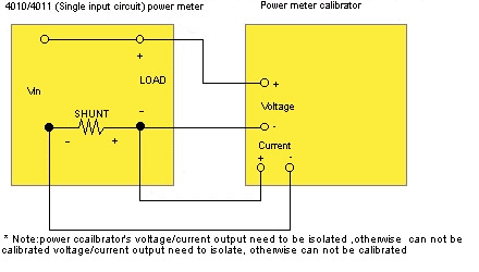
Figure 4: 4010/4011 single input circuit calibration connecting circuit
If there is no specific instruction, usual calibrator negative connector circuit connect to ground. Even though it doesn't affect the traditional power meter which using PT/CT isolation technique (shown in figure 5), but not for 4010/4011, the problem is that they cannot match, as describe in figure 5:
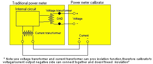
Figure 5: Traditional power meter's calibration connecting circuit
After 4010/4011 change from single input circuit to differential input circuit, its voltage input and current measuring is not connected together inside the power meter anymore, therefore during calibration it doesn't matter if the calibrator's voltage and current input is insulate or using the same ground, as describe in figure 6:
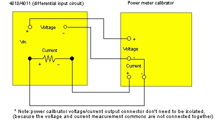
Figure 6: The calibration circuit connection of differential input 4010/4011 power meter
1.2. Accessories changes:
4010/4011 accompany accessories test adapter provide 4010/4011 simple plug into house hold electricity and simple load connection, and because the changes in input circuit to differential input circuit, accessory also change accordingly. In the mean time, internal connection is done according to the operator known connection method, plus providing system connection on the case for reference, the rear panel of 4010/4011 connector are shown as follow:
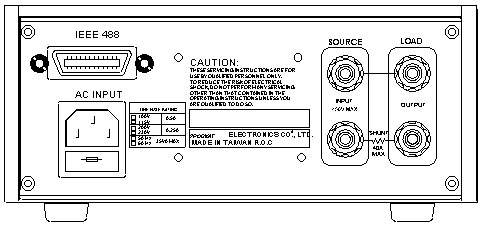
Figure 7: 4010/4011 single input circuit rear panel connection
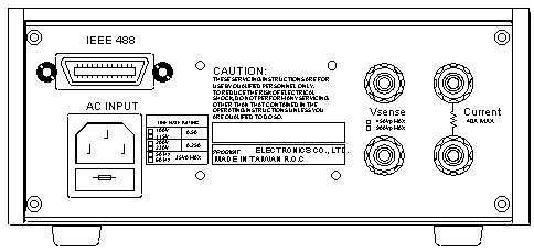
Figure 8: 4010/4011 differential input circuit rear panel connection
Test adapter connection figure description:
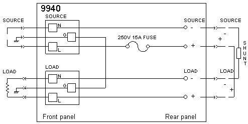
Figure 9: 4010/4011 single input circuit's schematic diagram for internal connection
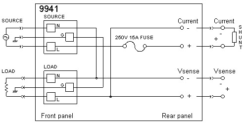
Figure 10: 4010/4011 differential input circuit's schematic diagram for internal connection
2. Frequency lock loop change from Analog Feedback Circuit to Digital Feedback Circuit:
2.1. Theory Description:
4010/4011 use Analog Feedback Circuit to get voltage/current waveform sampling frequency to 256 times of line frequency. Its voltage, current A/D resolution is 12 bit for each sampling. In another word, if input voltage frequency is 50 Hz, its voltage/current sampling frequency is 12.8 KHz, if 60 Hz, then it will be 15.36 KHz. If sampling frequency can synchronize with input voltage frequency, its block diagram will be like figure 11:
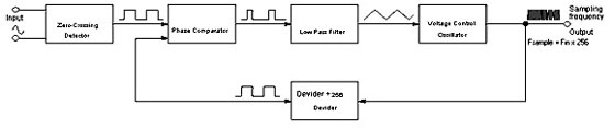
Figure 11: Analog Feedback Circuit block diagram
Digital Feeback Circuit function has the same function as Analog Feedback Circuit; its block diagram is shown in figure 12:
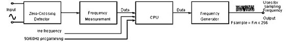
Figure 12: Digital Feedback Circuit block diagram
2.2. Function of Digital Feedback Circuit:
Digital Feedback Circuit with Central Processing Unit (CPU), the function produce can be increased, detail describe as follow:
2.2.1. Output 256 times frequency signal has the same width, every sampling sample has equal period, so that when calculating Vrms, Arms, Watt and PF, it will guarantee the error cause by the sampling width is different for each sample. This is the biggest improvement from Analog Feedback Circuit, because Analog Feedback Circuit use low pass filter's voltage to control oscillator (VCO), and Voltage control oscillator (VCO) output frequency need to be divided by 256 times and compare to input frequency in order to become a complete feedback circuit. From voltage control oscillator (VCO) output can acquire F(in) X 256 frequency sampling signal, as in reality, low pass filter's output is a tiny triangle ripple on DC voltage, this is because of the result form the process of comparison. And because of this, it also causes higher voltage control oscillator (VCO) output frequency at the peak of the triangle ripply, lower output frequency when it is at the low point of the ripple. Although within one period the input frequency, voltage control oscillator (VCO) output is 256 times of the input frequency, the sampling frequency is not equally divided. It changes according to the input voltage of the voltage control oscillator (VCO), as describe in figure 13. This result will cause small error under certain circumstances, including low power condition, or phase shift in voltage and current waveform is substantial
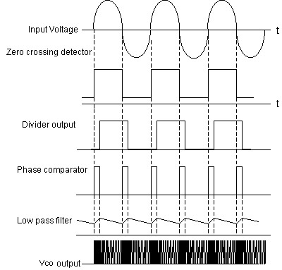
Figure 13: Analog Feedback Circuit waveform
2.3. Test Result:
According to 4010/4011 actual testing result, its current, power and power efficiency will encounter minor error at 0.5 or higher power factor, within +/-0.003, but drop to +/-0.012 error when power factor drop to 0.1 to 0, which all cause by the Analog Feedback Circuit. After upgrading to Digital Feedback Circuit with Prodigit special design circuit, making the 256 times frequency output sampling period equally divided, eliminate error from sampling unequally using analog feedback circuit, left only 12 bit A/D converter error, which cause the higher error within +/-0.002, 6 times better than before. Increase the accuracy of measurement during test, its function difference is shown at following figure.
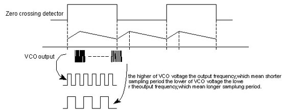
Figure 14: Analog Feedback Circuit (each sampling width is not the same exactly)

Figure 15: Digital Feedback Circuit (each sampling width is the same exactly)
2.4. The advantages of Digital Feedback Circuit
2.4.1. Digital Feedback Circuit use frequency generator to generate equal length's sampling frequency, improve over uneven output frequency generate by voltage control output (VCO) in Analog Feedback Circuit.
2.4.2. Digital Feedback Circuit can lock onto wider frequency range, less limitation, actually only limit by limitation in frequency detector and frequency generator; as for Analog version is limit within certain frequency range, like 45-46 Hz frequency range, otherwise feedback circuit can not lock onto it, and unable to generate stable output frequency.
2.4.3. For no input signal or DC measurement (like no connection or floating), operator can manually set sampling frequency or allow it to automatically switch, set the sampling frequency to 50 Hz, 60 Hz, or synchronize with line frequency. Therefore the sampling frequency can synchronize with line frequency, eliminate line (50/60 Hz) frequency disturbance, therefore, it can get more stable and accurate results.
2.4.4. For input signal with only two or more zero crossing (for example UPS output frequency), can cause input frequency rectifier circuitry produce frequency two times the actual frequency, causing sampling frequency error (mistaken for 100 Hz or 120 Hz), under this circumstance, operator can set sampling frequency to 50Hz, 60Hz or synchronize with household line frequency, therefore it is suitable for any situation, for detail operation setting, please refer to 4010/4011 operator manual.