
Application Notes-403
How to test Noise from the Output of Power Supply.
1. Forewords:
Nowadays, switching power supplies have replaced traditional
linear power supply; become the power source of most electronics equipment.
It is being used in the desktop computer, monitor, printer, notebook
computer, fax machine, photocopy machine and etc. The reason is because the
advantage of smaller size, weight less and high efficiency, however, the bad
thing of it is the noisy output. This article will discuss about the noise
in switching power supply with DC output.
1.1.
Definition:
Definition of output noise: the noise looks like a sine wave which overlaps
on the DC output, this sine wave contain PARD (Periodic and Random
Deviation) noise and it looks like the wave in Figure 1.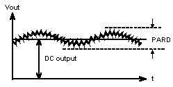 Figure 1
switching power supply's output noise
Figure 1
switching power supply's output noise
Since
switching power supply use high switching frequency (>20kHz), accompany by
PWM (Pulse Width Modulation) and output filtering circuit, it can transform
the household electricity (AC) into DC voltage which IC circuit need, for
example +5V, +12V, -5V, -12V, +3.3V, and so on. The only problem with the
switching power supply is some sine wave in the DC output. If this sine wave
(will call noise from now on) is large enough, it will cause malfunction in
the application circuitry. We use 5V for example, if the noise is 1.0Vp-p,
it will exceed the 4.75V-5.25V tolerance (a normal working voltage for logic
IC), which can cause malfunction or system shutdown, therefore output noise
has a lot of influence. Normally the output noise of switching power supply
is control under 1% of the output voltage, for example for +5V, +12V, its'
output noise specification should be 50mVp-p and 120mVp-p.
1.2. Controlling Output Noise:
When developing a switching power supply, the output noise has to be set
within a certain specification. During production, things like the parts
(such as transformer, diode, filtering capacitor and so on) with different
material, incorrect assemble, missing parts and so on that cause noise level
over the specification. To avoid these problems, checking output noise of
each switching power supply is a must during quality control.
2. Output Noise Testing:
The testing equipment can be either oscilloscope or
ripple/noise meter, the differences are describe as follow:
2.1. Oscilloscope:
This is the most popular equipment use for testing, but pay attention to
following condition otherwise the test result will not be accurate.
2.1.1. Avoid Ground Return: Differential input oscilloscope should be used,
because the BNC negative input in general oscilloscope is connected to the
case of the oscilloscope, and the case of the oscilloscope is connected to
outside line ground. If use a probe to measure the DC output, it can cause
ground return current which will affect the measurement. Because of that,
ground return should be avoided. Using a differential oscilloscope or
oscilloscope with a external differential
amplifier is the correct method for testing connection, see figure 2, INTEL
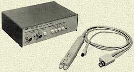
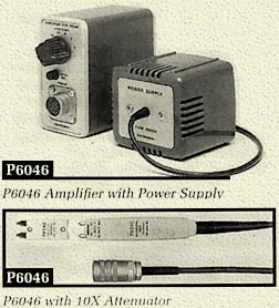
suggested test connection method. Figure 3, HP suggested test connection
method. Both INTEL and HP suggestion use differential oscilloscope; HP
differential amplifier is shown in figure 4, as Tek
differential probe is shown in figure 5.
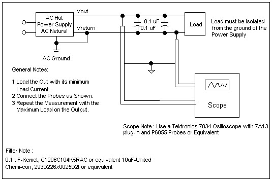 Note:
7A13 plug-in is differential amplifierFigure 2
PARD differential mode test connection diagram suggested by INTEL
Note:
7A13 plug-in is differential amplifierFigure 2
PARD differential mode test connection diagram suggested by INTEL
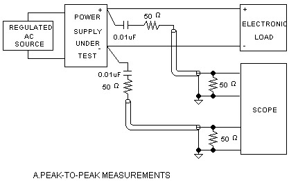
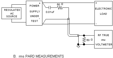
2.1.2. Test Condition:
When adding capacitor to the terminal during test, the
capacitor should be mentioned which include its material, capacitance and
etc., like figure 2 which INTEL add 10uF and 0.1uF capacitor in order to
simulate the capacitance on the main board. There is no rule set for this
test procedure; it is all depend on the condition. The capacitor should be
mentioned if it is used during test, like figure A and figure B recommended
connecting method, otherwise there will be big difference in the test
results.
2.1.3.
Frequency Bandwidth:
The frequency bandwidth of the oscilloscope will affect the
test result, usually the standard is 20MHz, or 30MHz (INTEL test
requirement), and the sampling frequency for digital oscilloscope should be
more than twice of the PARD frequency.
2.1.4.
Input Resistance:
Usually we use 50 Ohm. For low input resistance like 50 (the oscilloscope
can be set to 1M) at the terminal for the purpose of eliminating the signal
interference. There is no specific requirement for this part, but the input
resistance should be mentioned, otherwise there will be big difference in
the test results too.
2.2 Ripple
and Noise Meter:
Due to the reason that most of the oscilloscope have only two
channel, it would be difficult to monitor the power supply with many output,
addition disadvantage like it need human eye to observe and compare, and
high cost. Therefore using Prodigit 4030 (up to
4 channel) with ripple noise meter, it can do the test in one time with
upper and lower limit shown, plus the cost is reasonable (much cheaper than
oscilloscope), so this is a very good test equipment, 4030 function block
diagram is shown in figure 6. Its main specification is described as below:
4030 Ripple/Noise (Peak to Peak) Meter Block Diagram
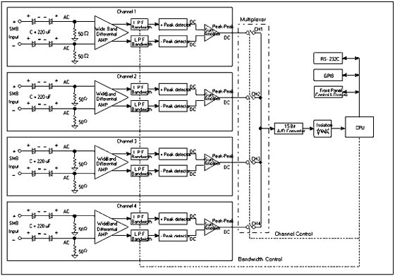
2.2.1.
Input Structure:
Like the oscilloscope description, the connection should
avoid ground return, therefore It is necessary to
use differential mode, and the input resistance normally is 50W (which can
effectively eliminate the input noise).
2.2.2.
Input Range:
Usually, the specify noise for DC switching power supply
output is 1% of its DC output, for example 5 volts DC output, its output
noise should be less than 50mVp-p, for 12 volts DC output, the noise should
be below 120mVp-p. Prodigit 4030 has 3 input
range options to choose from when order, they are 3.0Vp-p, 1.5Vp-p, 0.75Vp-p
respectively. Normally for 5V, 12V system voltage, choosing option with
0.75Vp-p input range should be enough, for 24V, 48V system voltage, 1.5Vp-p
or 3.0Vp-p option should be chosen.
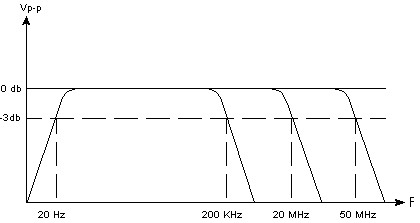
2.2.3.
Frequency Bandwidth:
Prodigit
4030 Ripple/Noise meter include 3 frequency bandwidth for user to choose
from, they are 20Hz~200KHz, 20Hz~2MHz and 20Hz~50MHz. 20Hz~50MHz is mainly
for checking output noise, 20Hz~200KHz or 20Hz~2MHz is for checking output
ripple or dynamic load over-shoot or under-shoot. Frequency bandwidth range
of 20Hz~50MHz means 4030 meter can measure the response of peak to peak
frequency range in input signal (noise). It usually means -3dB (0.707 X)
frequency range. For example if the input signal is 100mVp-p, at 50 MHz,
4030 will measure 70.7mV or more. 4030 Ripple/Noise meter classic frequency
respond is shown in figure 7.
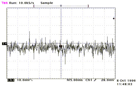
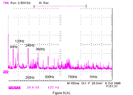
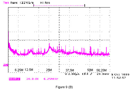
Power supply output noise includes many different frequency (like 50Hz, 60Hz ripple on off frequency) and other noise. If output noise has narrow and sharp FET with ON/OFF spike, it will contain many high frequency, we can use Spectrum Analyzer to observe the frequency contain, figure 8, 9 are the power supply output noise wave form and spectrum. When using 4030 Ripple/Noise meter to measure noise, picking different frequency bandwidth will cause its value to change. Normally, high frequency bandwidth (20Hz~50MHz) will result in higher value than using low frequency bandwidth.
2.2.5.
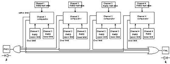
How to Define Pass/Fail with 4030
4030 has the ability to measure and compare between the upper and lower
limit. In every single PARD measure channel, when measure value is within
upper and lower limit, it will give a GO or Pass, if measure value is
outside the upper and lower limit, it will give a NG or Fail; if all four
PARD measure channel pass, green LED that shows PASS on the panel will light
up, if there is one fail the red LED that shows FAIL will light up on the
panel, to show that it doesn't pass the test condition. Every 4030 PARD
measuring channel has its own upper and lower limit value, operator can set
its value individually, and its PASS/FAIL comparison function block diagram
is shown in figure 10.
Note: 4030 panel will light up green PASS LED when pass, red FAIL LED will
light up when fail.
If using logic symbol to represent, the result will be like
as follow:
PASS = (PARD1L!OPARD1!OPARD1H) AND (PARD2L!OPARD2!OPARD2H)
AND (PARD3L!OPARD3!OPARD3H) AND (PARD4L!OPARD4!OPARD4H)
FAIL = (PARD1L!OPARD1) OR (PARD1!OPARD1H) OR (PARD2L!OPARD2) OR
(PARD2!OPARD2H) OR (PARD3L!OPARD3) OR (PARD3!OPARD3H) OR (PARD4L!OPARD4) OR
(PARD4!OPARD4H)
2.2.6.
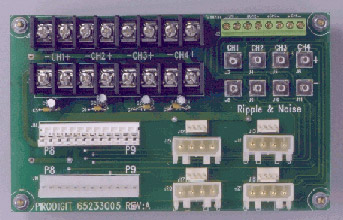
Checking Connecting Cable:
4030 includes eight SMB high frequency cable and sixteen SMB connector, providing connection between 4030 Ripple/Noise meter and test power supply, its connecting method can be found in 4030 operating manual. Prodigit also prepare the optional fixture Model 9951 (P/N: 65233005), cost US$10.00 /pc, which is shown in figure 11 for PC power supply, so that the user immediately connect the power supply to the 4030
3. Conclusion:
3.1.
Suitability:
4030 Ripple/Noise meter include four channel of noise measure
circuit; it can measure four output from power
supply simultaneously. If the output of the power supply is more than four
set, two 4030 can provide up to 8 set of noise measurement simultaneously,
therefore it will solve insufficient input channel problem.
3.2. Input Structure:
4030/3600A equipment with differential input structure, which can avoid
ground return problem, addition advantage like the low cost and ease of use.
This can improve the problem of expensive differential probe and hard to
use.
3.3. Definition:
4030/3600A equipment with PASS/FAIL define mechanism which improve the
difficulty in defining pass and fail using oscilloscope. This is very
suitable for quality control and checking on production line.
3.4. System Expansion:
4030 equipment with RS-232C & GPIB interface, and 3600A equipment with
RS-232C interface, which can use program to control. It is suitable for
manually, computer, or automatic control testing.