Application Notes-700
Using 7550
Precision Current Shunt
Prodigit Model 7550 Precision Current Shunt has five ultra stable and precision Resistors (0.001, 0.01, 0.1, 1, and 10 Ohms). It is designed to measure AC & DC currents ranging from 0.02A to 220A.
The theory of AC & DC current measurement is the Ohm's law "I = V/R ", the voltage drop is proportional to the current flow through the Resistor. Because of its five resistors Prodigit's Current Shunt is very stable and precise. Resistor values allow for reliable and accurate reading of current flow.
Voltage drop is fed to the front panel's "VOLTAGE OUTPUT" binding post and internal 4 1/2 Digit AC & DC Current Meter. The front panel's "RANGE SELECTOR" key switches one of the five shunt voltages to the VOLTAGE OUTPUT and 4 1/2 digital current meters. The AC & DC key displays either AC (True RMS) or DC current on the 4 1/2 DCM.
A 5 1/2 or higher Digit volt meter can be connected to the VOLTAGE OUTPUT of the 7550 when higher accuracy and resolution current reading is required.
The 7550 Precision Current Shunt operates as an AC & DC current meter of a DMM (Digit Multi-Meter), but with higher accuracy (<0.01%), better Temperature Coefficient (<10 ppm! CC, and much wider range (up to 220A).
Applications:
1. Current source calibration
2. Current meter calibration
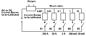
3. Current sensor calibration
4. Power supply output current calibration
5. Electronic load current meter calibration
1. Current source
calibration
The 7550 Precision Current Shunt provides better accu-
racy and more stability than most stable current sour-
ces, making it suitable for calibrating other current
sources. The connection diagram shows how to calibrate
AC or DC current source. The current sources connect to
the Precision Current Shunt directly, each Shunt resi-
stor is used separately to calibrate its current range,
this allows for the best accuracy in the 20mA to 220A
range.
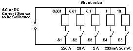
For a very stable but not precision enough current source, the current source, current meter and current shunt should be put in series. The reading on the current shunt acts as a standard reading. The calibration procedure is as follows:
a. Select the appropriate current shunt range by S1 to S5.
b. Program current source output until the current reads the rated testing current.
c. Adjust the current meter (U.U.T to be calibrated) until its reading is same as the current shunt's reading.
d. Repeat procedure a- c for different range, if required.
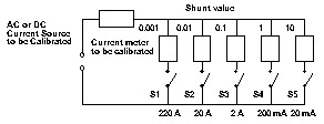
For a very stable but not precise enough current source, the current source, current sensor and current shunt should be put in series. The reading on the current shunt acts as a standard reading. The calibration procedure is as follows:
a. Select the appropriate current shunt range by S1 to S5.
b. Program current source output until the current reading on current shunt is the rated testing current.
c. Adjust the current sensor (U.U.T to be calibrated) until its reading is the same as the current shunt's reading.
d. Repeat procedure a - c for different range, if required.
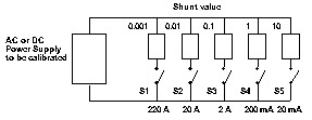
In the CC mode the Current shunt can be used to verify a Power Supply's output current stability and to calibrate its current meter. Test procedure is described below:
a. Select the appropriate current shunt range.
b. Program the CC output current from zero to the rated testing current.
c. Verify the current output stability of the Power Supply by comparing the reading deviation of the shunt's current reading.
d. Calibrate and adjust the Power Supply's current meter to the shunt's current reading.
e. Repeat procedure a - d for different range, if required.
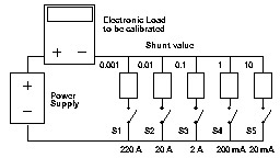
Normally, the current source output compliance voltage is less than 3V (even lower than 1V), limiting its output VA capacity. While it may be no problem to calibrate a current meter or current sensor with a very low input impedance, it is a problem to calibrate an Electronic Load with normal operating voltage of more than 3V. The current source can not supply its output current on such compliance voltage. To solve the compliance voltage problems on the current source, the following connection diagram uses an Electronic Load and Current Shunt to replace a current source. The Current shunt can be used to verify the output current's stability of an Electronic load in CC mode and to calibrate its current meter. Test procedure is described below:
a. Select the appropriate current shunt range by S1 to S5.
b. Program the Electronic load's CC (Constant Current) output current from zero to the rated testing current. Adjust the Power supply's output voltage higher than the minimum operating voltage on the Electronic Load to be calibrated (U.U.T).
c. Verify the current output stability of Electronic Load by comparing the reading deviation of the shunt's current reading.
d. Calibrate and adjust the Electronic Load's current meter to the shunt's current reading.
e. Repeat procedures a - d for different range, if required.